New Mexico Scientific
Yes, I have finally started adding projects. To get things started I wanted to create a project using some of the things I already had laying around as well as NOT use an Arduino!!! So many times projects are overkill using an Arduino when a simple pic would do.
I happen to have some Picaxe 08M 8pin pics laying around and decided to do something with them. I decided to re-visit a very old project I had from high school and give it a refresh. Create a VERY SIMPLE RF Signal Strength Meter.
The summary of the project is:
Breadboard a 5V supply, then add the 08M, use 3 LEDs for the indicators, and add what was needed to detect a RF signal and use the ADC input of the 08M to determine basic signal level. Shouldn't be too hard. In fact, it wasn't.
NOTE: This project was done on a Sunday with the purpose of not only something to do but also to try and get used to using Fritzing, picaxe programming, and to fire up the old 40w laser cutter to see if it can make PCB worth using.
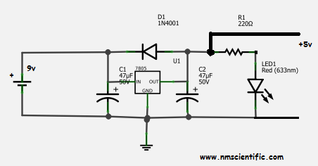
I won't go into detail on the 5v supply but it takes a 9v input, and spits out 5v. Here is the schematic:
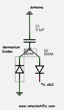
The RF Signal detector was the easiest, 3 components, and 1 is only if you want to add it. All you need is two Germanium Diodes, and a .1uf cap if you so desire. I ended up not using it as it was more sensitive without it; however, I can add it on the Antenna wire at any point if I decide I actually do need it.
Now, I was going to try and increase the sensitivity with an op amp, but all I had was a 741 and after a few tries it did not seem to increase anything but my frustration. 4.26v output from it no matter the input... Anyways, I'm not an expert at anything so I'm sure I was doing something wrong.. Anyways, back to the build.
I am still getting used to Fritzing software and only used it this Sunday so I will show you what I have and please excuse the messy schematic and PDB layout.
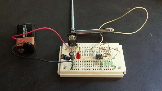
Here is a picture of the working breadboard of the 08M based RF Strength Meter:
Here is the schematic I was able to get from Fritzing software:
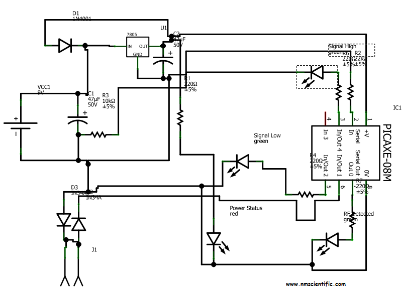
SCARY UGLY thing isn't it? I obviously need to get the auto route to work better for me. Again, I know its all in how you do it and I do it bad right now. But the software does have lots of standard parts including the PICAXE, Arduino, SparkFun items, etc built in.
Anyway, here is a short video of a test run. Then I will show you how the PCB went. I was pleased with how easy it was, but first, the demo:
Here is the CODE:
		        Here is the CODE:
###################
main:
readadc 1,b1

if b1 <= 1 then goto nosignal
if b1 >= 2 then goto signal

pause 500
goto main

nosignal:
low 0
low 2
low 4
goto main

signal:
high 0
if b1 >= 4 then goto signallow
pause 500
goto main

signallow:
high 0
high 2
if b1 >= 8 then goto signalhigh
pause 500
goto main

signalhigh:
high 0
high 2
high 4
pause 500
goto main
##################
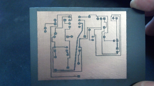
Ok, so there you go. You can adjust the display via simple code for the PIC. Now, Fritzing also had a PCB section. I stumbled around it for a bit and came up with something 'usable'. You can export as SVG, PDF, standard or mirrored. I exported the PCB as a mirrored PDF, imported it in GIMP, and inversed the image so it was white traces on a black background. I did this so that my laser cutter could cut away the black parts and only leave the the white traces. Now, why?
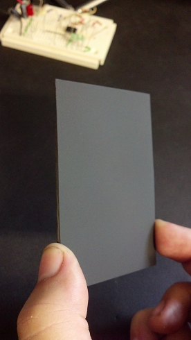
I took a PCB, cleaned the copper and then applied 2 coats of flat black paint to it. Then I used my laser cutter to cut away the paint everwhere I did NOT want copper. This worked out better than I expected.
After a couple of coats I engraved it at speed 30 power 70 to cut the paint away.
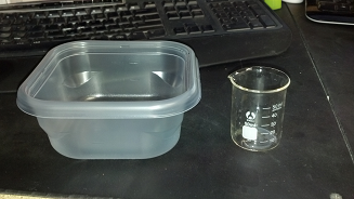
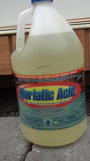
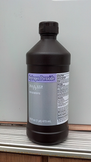
I used a plastic container and measured 30ML of Muriatic Acid ($5 at the local pool supply store) along with 60ML of 3% Hydrogen Peroxide ($.58 cents at wal-fart), put my board in, waited about 20 min, and all the exposed copper was gone.
A quick rinse, and I wiped the paint off with a cloth and just a dab of Acetone. Took about 20 seconds to wipe it clean. Rinsed everything and this was the result:
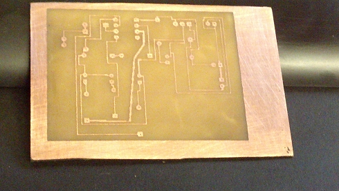
Yes, look at all that extra copper! I made the board big as I had never done this before with a laser cutter so did not know what to expect from the Laser. I will cut the extra off before mounting it in an enclosure.
Thats pretty much it for now. I have a nice enclosure I have had in my box of enclosures with a nice 9V section and everything, but again, its "to nice" and overkill for this so if I find a smaller enclosure I will use that and add the finished product here.
I have many things in the works now and will be documenting them for your distraction.
I have a PICAXE 08M roving robot with PING sensor as my next Sunday project. Will also have a homemade Van De Graff, advanced sentry robot with airsoft offensive weapons. But first, what can I do with my 1500mw laser pointer? Turns out, a 1500mw, yes over 1.5 watt laser pointer is not as fun as you might think. you can't look at where you point it without going blind unless you have safety laser glasses on and it tends to start to burn things within a few seconds... I'll figure out something. Send me your suggestions.